ADT7463
http://onsemi.com
23
SMBALERT
Interrupt Behavior
The ADT7463 can be polled for status, or an SMBALERT
interrupt can be generated for outoflimit conditions. It is
important to note how the SMBALERT
output and status
bits behave when writing Interrupt Handler software.
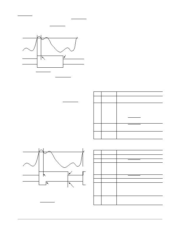
Figure 34. SMBALERT
and Status Bit Behavior
HIGH LIMIT
TEMPERATURE
STICKY
STATUS BIT
SMBALERT
CLEARED ON READ
(TEMP BELOW LIMIT)
TEMP BACK IN LIMIT
(STATUS BIT STAYS SET)
HIGH LIMIT
TEMPERATURE
STICKY
STATUS BIT
SMBALERT
Figure 34 shows how the SMBALERT
output and
sticky
status bits behave. Once a limit is exceeded, the
corresponding status bit gets set to 1. The status bit remains
set until the error condition subsides and the status register
gets read. The status bits are referred to as sticky since they
remain set until read by software. This ensures that an
outoflimit event cannot be missed if software is polling
the device periodically. Note that the SMBALERT
output
remains low for the entire duration that a reading is
outoflimit and until the status register has been read. This
has implications on how software handles the interrupt.
Handling SMBALERT
Interrupts
To prevent the system from being tied up servicing
interrupts, it is recommend to handle the SMBALERT
interrupt as follows:
1. Detect the SMBALERT
assertion.
2. Enter the interrupt handler.
3. Read the status registers to identify the interrupt
source.
Figure 35. How Masking the Interrupt Source Affects
SMBALERT
Output
HIGH LIMIT
TEMPERATURE
STICKY
STATUS BIT
SMBALERT
CLEARED ON READ
(TEMP BELOW LIMIT)
TEMP BACK IN LIMIT
(STATUS BIT STAYS SET)
INTERRUPT
MASK BIT SET
INTERRUPT MASK BIT
CLEARED
(SMBALERT
REARMED)
4. Mask the interrupt source by setting the
appropriate mask bit in the interrupt mask registers
(Reg. 0x74, 0x75).
5. Take the appropriate action for a given interrupt
source.
6. Exit the Interrupt Handler.
7. Periodically poll the status registers. If the
interrupt status bit has cleared, reset the
corresponding interrupt mask bit to 0.
This causes the SMBALERT
output and status bits
to behave as shown in Figure 35.
Masking Interrupt Sources
Interrupt Mask Registers 1 and 2 are located at Addresses
0x74 and 0x75. These allow individual interrupt sources to
be masked out to prevent SMBALERT
interrupts. Note that
masking an interrupt source only prevents the SMBALERT
output from being asserted; the appropriate status bit gets set
as normal.
Table 29. INTERRUPT MASK REGISTER 1
(REG. 0X74)
Bit
Mnemonic
Description
7
OOL
1 masks SMBALERT
for any alert
condition flagged in Status Register 2.
6
R2T
1 masks SMBALERT
for Remote 2
temperature.
5
LT
1 masks SMBALERT
for Local
Temperature.
4
R1T
1 masks SMBALERT
for Remote 1
Temperature.
3
5V
1 masks SMBALERT
for 5 V channel.
2
V
CC
1 masks SMBALERT
for V
CC
channel.
1
V
CCP
1 masks SMBALERT
for V
CCP
channel.
0
2.5V
1 masks SMBALERT
for 2.5 V channel.
Table 30. INTERRUPT MASK REGISTER 2
(REG. 0X75)
Bit
Mnemonic
Description
7
D2
1 masks SMBALERT
for Diode 2 errors.
6
D1
1 masks SMBALERT
for Diode 1 errors.
5
FAN4
1 masks SMBALERT
for Fan 4 failure. If
the TACH4 pin is being used as the
THERM
input, this bit masks
SMBALERT
for a THERM
event.
4
FAN3
1 masks SMBALERT
for Fan 3.
3
FAN2
1 masks SMBALERT
for Fan 2.
2
FAN1
1 masks SMBALERT
for Fan 1.
1
OVT
1 masks SMBALERT
for
overtemperature (exceeding THERM
limits).
0
12V/VC
1 masks SMBALERT
for 12 V channel
or for a VID code change, depending on
the function used.
发布紧急采购,3分钟左右您将得到回复。
相关PDF资料
ADT7476AARQZ-R
IC REMOTE THERMAL CTLR 24QSOP
ADT7481ARMZ-1RL
IC SENSOR TEMP 2CH ALARM 10MSOP
ADT7482ARMZ-REEL
IC SENSOR TEMP 2CH ALARM 10MSOP
ADT7485AARMZ-R
IC TEMP/VOLT DGL SENS SST 10MSOP
ADT7486AARMZ-RL
IC TEMP SENS DGTL 2CH SST 10MSOP
ADT7488AARMZ-RL
IC TEMP/VOLT DGTL W/SST 10MSOP
ADT7518ARQZ
IC SENSOR TEMP QD ADC/DAC 16QSOP
AT30TS00-MAH-T
SENSOR DGTL TEMP I2C/SMBUS 8WDFN
相关代理商/技术参数
ADT7463ARQZ-REEL7
功能描述:IC REMOTE THERMAL CTRLR 24-QSOP RoHS:是 类别:集成电路 (IC) >> PMIC - 热管理 系列:dBCool® 标准包装:1 系列:- 功能:温度监控系统(传感器) 传感器类型:内部和外部 感应温度:-40°C ~ 125°C,外部传感器 精确度:±2.5°C 本地(最大值),±5°C 远程(最大值) 拓扑:ADC,比较器,寄存器库 输出类型:2 线 SMBus? 输出警报:无 输出风扇:无 电源电压:2.7 V ~ 5.5 V 工作温度:-40°C ~ 125°C 安装类型:表面贴装 封装/外壳:SOT-23-8 供应商设备封装:SOT-23-8 包装:Digi-Reel® 其它名称:296-22675-6
ADT7466
制造商:AD 制造商全称:Analog Devices 功能描述:dBCool Remote Thermal Controller and Voltage Monitor
ADT7466ARQZ
功能描述:板上安装温度传感器 RMT THRM CTR VLT MON RoHS:否 制造商:Omron Electronics 输出类型:Digital 配置: 准确性:+/- 1.5 C, +/- 3 C 温度阈值: 数字输出 - 总线接口:2-Wire, I2C, SMBus 电源电压-最大:5.5 V 电源电压-最小:4.5 V 最大工作温度:+ 50 C 最小工作温度:0 C 关闭: 安装风格: 封装 / 箱体: 设备功能:Temperature and Humidity Sensor
ADT7466ARQZ-REEL
功能描述:板上安装温度传感器 RMT THRM CTR VLT MON RoHS:否 制造商:Omron Electronics 输出类型:Digital 配置: 准确性:+/- 1.5 C, +/- 3 C 温度阈值: 数字输出 - 总线接口:2-Wire, I2C, SMBus 电源电压-最大:5.5 V 电源电压-最小:4.5 V 最大工作温度:+ 50 C 最小工作温度:0 C 关闭: 安装风格: 封装 / 箱体: 设备功能:Temperature and Humidity Sensor
ADT7466ARQZ-REEL7
功能描述:IC REMOTE THERMAL CTRLR 16QSOP RoHS:是 类别:集成电路 (IC) >> PMIC - 热管理 系列:dBCool® 标准包装:1 系列:- 功能:温度监控系统(传感器) 传感器类型:内部和外部 感应温度:-40°C ~ 125°C,外部传感器 精确度:±2.5°C 本地(最大值),±5°C 远程(最大值) 拓扑:ADC,比较器,寄存器库 输出类型:2 线 SMBus? 输出警报:无 输出风扇:无 电源电压:2.7 V ~ 5.5 V 工作温度:-40°C ~ 125°C 安装类型:表面贴装 封装/外壳:SOT-23-8 供应商设备封装:SOT-23-8 包装:Digi-Reel® 其它名称:296-22675-6
ADT7466ARQZ-RL7
功能描述:板上安装温度传感器 RMT THRM CTR VLT MON RoHS:否 制造商:Omron Electronics 输出类型:Digital 配置: 准确性:+/- 1.5 C, +/- 3 C 温度阈值: 数字输出 - 总线接口:2-Wire, I2C, SMBus 电源电压-最大:5.5 V 电源电压-最小:4.5 V 最大工作温度:+ 50 C 最小工作温度:0 C 关闭: 安装风格: 封装 / 箱体: 设备功能:Temperature and Humidity Sensor
ADT7466ZEVB
功能描述:BOARD EVALUATION ADT7466 RoHS:是 类别:编程器,开发系统 >> 过时/停产零件编号 系列:dBCool® 标准包装:1 系列:- 传感器类型:CMOS 成像,彩色(RGB) 传感范围:WVGA 接口:I²C 灵敏度:60 fps 电源电压:5.7 V ~ 6.3 V 嵌入式:否 已供物品:成像器板 已用 IC / 零件:KAC-00401 相关产品:4H2099-ND - SENSOR IMAGE WVGA COLOR 48-PQFP4H2094-ND - SENSOR IMAGE WVGA MONO 48-PQFP
ADT7467
制造商:AD 制造商全称:Analog Devices 功能描述:dBCool Remote Thermal Monitor and Fan Controller
